


Paravalvular leak (PVL) occurs when there is backflow around a prosthetic valve. This can occur through a variety of causes. Paravalvular Leak is accompanied by regurgitation and is often a significant problem for patients with bioprosthetic or mechanical heart valves.1 Often manifesting as heart failure (85 % of all presenting symptoms) and hemolysis (13–47 % of all presenting symptoms and signs),2,3 PVL has a prevalence rate as high as 5–17 % of all mechanical valves.4–6
The mechanism of leaks is not well understood. The alignment between sewing ring and annulus may be incomplete because of significant annular calcification. The tissue around valves can weaken as a result of chronic infection. Even the sutures themselves may not allow significant apposition of the valve with the annulus. All of these factors can lead to significant PVL.
How can PVL be treated? Unfortunately, repeat surgery portends a worse prognosis, with mortality rates for the first redo, second redo or third redo surgery of 13 %, 15 %, and 35 %, respectively2. Each repeat operation is less likely to be successful. Therefore there is ample room for percutaneous approaches.
It is important to select the right patients for PVL closure. Prior to beginning a case, it is important to exclude active infection, valve instability, and/or cardiac thrombus.5 Indications for PVL closure include patients with significant regurgitation accompanied by symptoms of congestive heart failure and/or hemolysis. Important contraindications to PVL closure may include presence of active local or systemic infection, active ischemia, mechanical instability of the prosthetic valve, intracardiac thrombus, and patients with a life expectancy due to comorbidities that is less than 6 months.
Paravalvular Leak: Imaging
Successful PVL closure begins with efficient imaging. There are a variety of methods available to diagnose PVL, including transthoracic echocardiography (TTE), transoesophageal echocardiography (TEE), computerised tomography (CT) and magnetic resonance imaging (MRI). Among these, there is no one optimal diagnostic method; each has significant advantages and disadvantages. The important pieces of information to ascertain during imaging are location, size, shape, severity and the number of leaks.
It is important to know the valve type prior to any imaging (often available from the surgical report), and it can also be helpful to know its orientation and the suturing technique that was used. Orientation of the valve varies, but often the preferred mitral orientation for tilting-disc valves is with the major orifice toward the left ventricular free wall as opposed to the septum. For the aortic position, the preferred orientation is with the major orifice to the right posterior aortic wall. Suturing techniques may also vary, ranging from non-everting mattress (with or without sub-annular pledgets), everting mattress (with or without supra-annular pledgets), simple interrupted, figure-of-eight, and continuous/running sutures. The choice of suture technique depends on valve type and surgeon preference.
Echocardiography allows for direct comparison of pre- and intra-procedural results. However, echocardiography is prone to artifact from prosthetic shadowing.7 Aortic PVL can be diagnosed and evaluated often by TTE, whereas mitral PVL often requires TEE (although TTE may be useful for original diagnosis). 3D echocardiography adds the ability to determine the path of a leak, which can often take a serpentine course. The authors perform all PVL interventions with TEE guidance (often with 3D characterisation of leak size and course).
CT and MRI add further information. Retrospective ECG-gated reconstruction allows diastolic and systolic characterisation. CT can also provide the accurate imaging angle for intervention and closure.Unfortunately, artifacts secondary to calcification or the valve can blur the leak itself, making it difficult to visualise. CT, in comparison to MRI, has better spatial resolution, however requires contrast dye and involves exposures to more radiation.8
Location
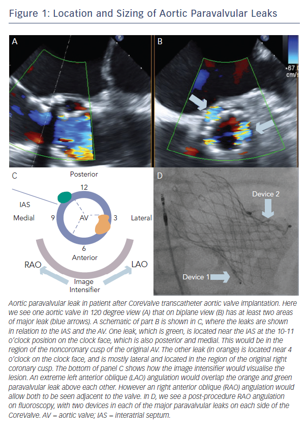
A clock face is often used to describe both aortic and mitral PVLs (Figure 1, Figure 2). The three commissures are assigned an hour on the clock face: between left and right coronary sinus is 5 o’clock, between right and non-coronary sinus is 8 o’clock, non-coronary and left coronary sinus is 11 o’clock. This lexicon helps in communication between imager and operator and also helps to monitor leaks pre- and post-closure. Statistically, aortic leaks are most often between 7 and 11 o’clock (46 %) and also between 11 and 3 o’clock (36 %) 9
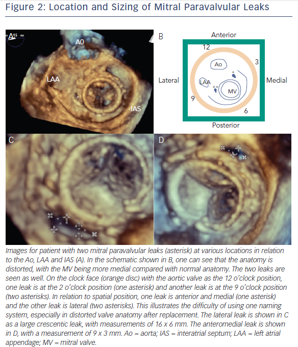
Both clock face and anatomical criteria can be used to describe mitral PVL location. Location is based on the mitral valve annulus and is described as medial, lateral, anterior or posterior. The clock face for the mitral valve starts at the 12 o’clock position between the aortic valve and mitral valve A2, then the 3 o’clock position is the posteromedial commissure and interatrial septum and the 6 o’clock position is the posterior annulus midpoint. According to this system, mitral PVL is found often between 10 and 2 o’clock (45 %) and between 6 and 7 o’clock (37 %).9
Sizing
Although the course of the leak may be serpentine, with an orifice that is crescentic or oval in shape, some assumptions can be made about size of the PVL. Echocardiography of the vena contracta of the leak can be used to estimate the size, although this method is not perfect. With the advent of 3D imaging, the leak can be measured in multiple directions. CT and MRI may provide more information if an echocardiogram is unclear. The authors do not recommend balloon sizing as it is associated with a risk of balloon rupture as a consequence of sharp edges due to annular calcium. Measurement of the leak will dictate the choice of device for PVL access, and in turn the delivery system guide or sheath size.
Paravalvular Leak: Access
Aortic or medial mitral PVLs can be approached by transfemoral access. The authors’ preference is to use a 0.035” wire, often a hydrophilic one (e.g. Terumo Glidewire, Terumo Medical Corporation, Somerset, NJ, USA) inside a 5 Fr diagnostic catheter (JR4 or MP). The wire crosses the leak and the catheter follows the wire. This wire is substituted for a stiff 0.035” wire (e.g. Amplatzer Extra Stiff Wire, St. Jude Corporation, Minneapolis MN, USA). The delivery system guide or sheath is then advanced over the stiff wire, which is then removed, and the device is placed in correct position. If more support is needed for the catheter or delivery system to cross the leak, a rail can be made (either by transseptal access and snare or by externalising the wire through transapical access). If the aortomitral curtain is crossed,
it is often necessary to protect this from significant stress by covering a bare wire with a catheter at all times. For a medial mitral leak, a JR4 or IM catheter can be helpful.
Sometimes transseptal access is needed, either for mitral PVLs or difficult aortic PVLs. Any transseptal system should be used, and
this should be performed under transoesophageal guidance.
The authors recommend an inferior and midway between superior and posterior position for puncture for most leaks, although it is just as important to make sure the transseptal puncture is performed safely as it is to find a specific spot to cross the septum that will allow crossing of the leak. For difficult aortic PVLs, the leak is crossed during retrograde femoral approach and a rail is formed by snaring the wire in the left atrium. For transseptal access, heparin 10,000 units should be administered.
When a mitral PVL cannot be crossed through other methods or if there are mechanical heart valves in both aortic and mitral positions, transapical access can be considered. In addition to echocardiographic/fluoroscopic visualisation to determine the position of the ventricular apex, it is also important to perform concomitant coronary angiography to avoid the coronary arteries. A sheath (often 4 Fr) is delivered and heparin is given. A device is often used to close the entry site (e.g. Amplatzer PDA Occluder, St. Jude Corporation). The authhors recommend this as a third and last option, as there is an increased risk of complications from tamponade, hemothorax or puncture of a coronary artery. Follow-up TTE and chest X-ray are highly recommended at 24 hours after procedure/discharge.
Paravalvular Leaks: Device Selection
There are only a few devices designed specifically for PVLs, thus other devices have often been used. The ideal device has the appropriate size and shape for the leak and does not interfere with the valve leaflets. Furthermore, it does not interfere with other vital structures, such as the coronary ostia in the case of aortic valves or left ventricular outflow tract in the case of mitral valves. Optimally, only one device is needed.
The device size is dependent on measurements from echocardiogram (TEE and 3D whenever possible). Angiography helps in the case of aortic PVL when this can be seen next to the valve. Some may use external catheter size to approximate leak size, but this is also dependent on calcification and tortuosity, which can cause difficulty in a catheter’s ability to cross the leak. The authors follow this general algorithm: for a small cylindrical leak, an Amplatzer Vascular Plug (AVP) II or PDA Occluder may be best; for an oval or crescentic leak, the AVP III is more ideal; if the leak is small or has significant angulation, an AVP IV is better as it is more flexible.
Recently, the Occlutech PLD (Helsingborg, Sweden) device has obtained CE mark approval. There are two devices, one square and one rectangular, both made of nitinol braided mesh. Waist size is chosen similar to the defect size, and this ranges from 3 to 7 mm with circular waist for the square device (requiring 5–7 Fr sheath) and from 4 x 2 to 12 x 5 mm for the rectangular device (requiring
5–8 Fr sheath).10
Putting it all together: Aortic Paravalvular Leak
Retrograde transfemoral approach is the optimal strategy for aortic PVL. TEE is used for imaging, with description of the leak on the clock face as described above. Once the leak is crossed with a hydrophilic wire, it is crossed again with a 5 Fr diagnostic catheter (often JR4, MP or Amplatz-1). Defect size determines device size, which dictates size of the guide catheter or long sheath to deliver the device. This is exchanged over a stiff wire (often Amplatz Extra Stiff) for a delivery system guide catheter or sheath (e.g. Cook Shuttle Sheath, Cook Corporation, Bloomington, IN, USA). The device is then delivered through this delivery system. TEE then assesses changes with the regurgitant jet. Prior to release, it is important to check for absence of coronary ostia coverage and free movement of the valve leaflets.
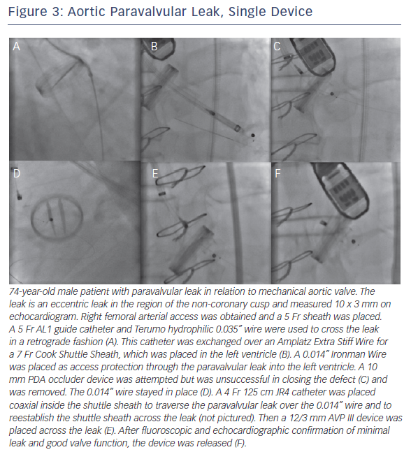
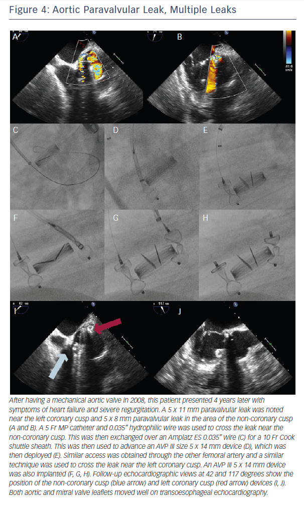
If there is significant tortuosity or difficulty crossing the leak, more support can be obtained by building a rail. A transseptal rail involves transseptal access with subsequent snaring of the original wire within the left atrium. An apical ventricular rail involves left ventricular puncture and having the wire through the apex. Figures 3 and 4 demonstrate aortic PVL closure.
Subsequent aortic angiography is often necessary to rule out coronary compression and evaluate the valve for regurgitation. The valve should not have an increased gradient and should have free-moving leaflets. If the device was implanted in the area of the non-coronary cusp, special attention should be given to the anterior mitral valve leaflet.
Putting it all together: Mitral Paravalvular Leak
After evaluating the leak with TEE, the first approach is to try the simplest approach: retrograde transfemoral approach with a 5 Fr IM or JR4 catheter and a hydrophilic 0.035” guidewire. Once this is across the leak, the wire can be exchanged for a stiff wire and then the delivery system (guide catheter or long sheath). The wire is removed, the device is advanced, and then the device is deployed. By deploying the first disc within the left atrium, it is simpler to visualise on TEE. If there is an issue with support, transseptal access with snare can be used to make a rail. As mentioned above, it is important to protect the aortomitral continuity with a catheter whenever possible.
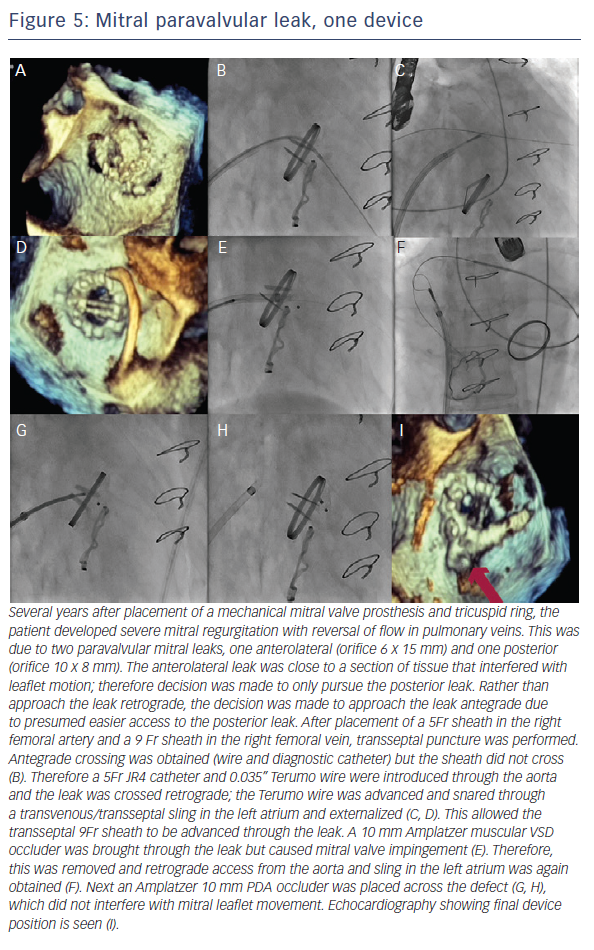
When the retrograde transfemoral approach is not successful, an antegrade transseptal approach can have some benefits. It is important to cross posteriorly to avoid the aorta and superiorly to have enough catheter room to reach both medial and lateral leaks. A similar approach with a 0.035” hydrophilic wire, 5Fr JR4 or MP catheter, stiff wire exchange, and then exchange for delivery system (guide catheter or long sheath) is used. If support is still an issue, a transarterial rail is recommended. Another option is to advance the transseptal sheath through the defect. Some centers have used an Agilis system (St. Jude Corporation) if the catheter is unable to reach the defect or if the puncture site was suboptimal. The advantage that this offers is increased steerability; the disadvantage is a larger transseptal puncture and increased cost of the procedure. Figures 5, 6 and 7 show examples of mitral PVLs.
After the device is placed, TEE should show mobile mitral leaflets, open pulmonary veins, and if the leak was anterior, an unobstructed mitral valve. Angiography is insufficient to make this determination. The authors do no recommend release of a device until these requirements are satisfied.
Device success
There are many ways to characterise device success, but the device should treat the problem it is there to solve – there should be a sizeable decrease in regurgitation and improvement in symptoms. The patient should have a TTE for aortic leak and TEE for mitral leak at 6 months (or earlier if symptoms are present). If there is hemolysis, the hemoglobin/hematocrit should also be monitored.
Special situations
Multiple leaks
In cases of multiple leaks, the authors recommend closing the major leak only at first, as if there is significant infection/hemolysis, the offending device can be identified. If multiple devices are placed, perhaps one is not the infectious source and therefore should not be removed. The authors place multiple devices or close multiple leaks if there is uncertain follow-up or with two equally sized large leaks.
One approach for multiple device placement is the same-sheath approach: both devices go through the same sheath one after the other. Device one crosses the leak and is deployed. Next, the wire and delivery catheter are used to cross the leak again, and the second device is advanced and deployed. With this method, only one access is needed. However, the first device needs to be fully released before the second device can be advanced.
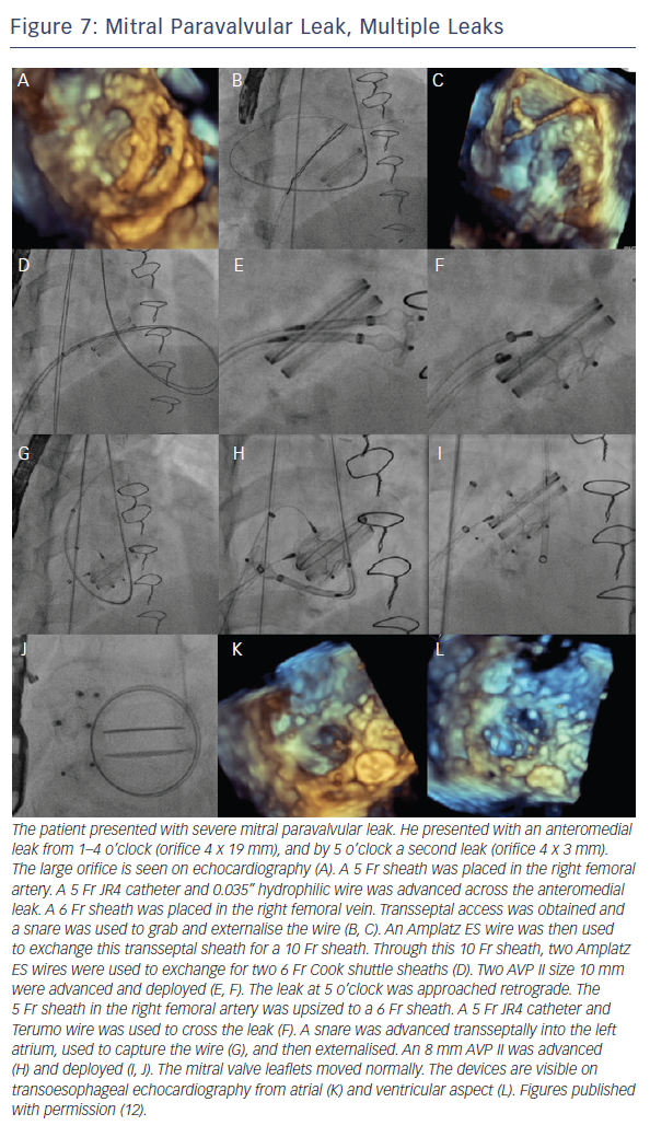
Another method is with new access. Contralateral femoral access and device advancement may be sufficient for aortic PVL (Figure 2). In the case of mitral PVL, this requires a transseptal approach and dilating the septal access point to accommodate a larger sheath. The larger sheath should be a sum of the sheaths required for the individual devices (if the two devices need two 6 Fr sheaths, the septum should be crossed with a 12 Fr sheath). Then two (or three wires for three devices) are used to cross the sheath, these wires are exchanged
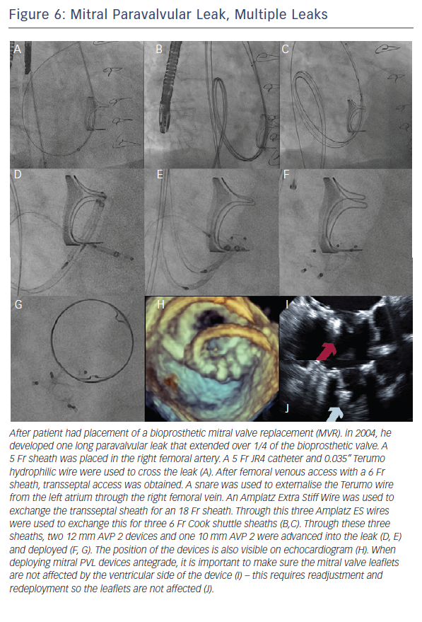
for stiff wires, and the prior large sheath is switched to the multiple delivery systems. The independent devices are then delivered (see Figures 4 and 5).
Preserving PVL access with device placement
When the wire crosses the leak only with great difficulty (e.g. tortuous anatomy and/or suboptimal transseptal catheter position), it is also possible to preserve PVL access during device placement with an 0.014” coronary wire (Figure 1). This allows the ability to preserve access – which is crucial if the device must be removed because it is not the correct size or causes leaflet compromise. However, this carries with it the risk that the wire will not be retrievable after the device is released.
Complications
Complications will occur but must be avoided when possible.
These include valve interference (3.5–5.0 %), stroke, endocarditis, post-procedural hemolysis, device erosion, emergent cardiac surgery (0.7–2.0 %) and death (1.4–2.0 %). One study showed major adverse events at 30 days (death, myocardial infarction, stroke, major bleeding and emergency surgery) at a rate of 8.7 %. Embolised devices from the aortic position are often large and go to the iliac bifurcation and can be removed percutaneously; those from the mitral position may be caught at the left ventricular outflow tract and may require surgery.
Devices that embolise from the aortic position may travel anywhere. Larger devices are less likely to locate cranially and are often found at the iliac bifurcation. The same holds true for devices that embolise from the mitral position, as most are small enough to pass through the left ventricular outflow tract and the aortic valve.
Post-procedural hemolysis is often due to shearing as blood flows through the now smaller orifice at a higher velocity. While this may worsen the clinical condition, this may also be well tolerated and resolves spontaneously after complete endothelialisation. This may take months.
Long-term survival
Technical success rate has reported as 77–86 %, and there has been 67–77 % clinical improvement. A study by Ruiz et al. reported long-term survival at 6, 12 and 18 months as 91.9, 89.2 and 86.5 %, respectively.8 Sorajja et al. found 1–2 year survival after PVL closure of 70–75 % with an estimated 3-year survival rate of 64.5 %.11